Flight & Camera Parameters for a Thermographic Inspection
Your Above Regional Operations Coordinator will supply kml polygons of each zone.
Example of site divided into "Inspection Zones". Note the higher Altitude "Overview Zone"
Flight Parameters
Ground-mounted Tables
Your assigned Regional Operations Coordinator will inform you which inspection level is required for each inspection.
🔎 🔎 🔎 3 cm/pixel GSD | 🔎 🔎 5.5 cm/pixel GSD | 🔎 <8 cm/pixel GSD | |||||||
Overlap % Front/Side | Altitude | ~area/flight | Overlap % Front/Side | Altitude | ~area/flight | Overlap % Front/Side | Altitude | ~area/flight | |
H20T + DJIPilot2 | 65/45 | 34m | 4.8ha | 65/45 | 62m | 15ha | 65/45 | 90m | 30ha |
H30T + DJI Pilot2 | 65/45 | 40m (2cm/px) | 12ha | 65/45 | 110m | 32ha | 65/45 | 120m (6cm/px) | 37ha |
M4T/D + DJIPilot2 | 75/45 | 30m | 7.8ha | 75/45 | 55m | 25ha | 75/45 | 80m | 50ha |
M3T/D + DJIPilot2 | 75/45 | 23m | 8.5ha | 75/45 | 42m | 27ha | 75/45 | 61m | 43ha |
M30T + DJIPilot2 | 75/45 | 23m | 3.0ha | 75/45 | 42m | 9.5ha | 75/45 | 61m | 21ha |
XT2 13mm + DJIPilot2 | 65/45 | 23m | ~ | 63/44 | 42m | ~ | 63/44 | 61m | ~ |
XT2 19mm + DJIPilot2 | 65/45 | 33m | ~ | 63/44 | 61m | ~ | 63/44 | 89m | ~ |
❗"Overlap values" are not actual image overlap ratios as DJI Pilot 2 does not compensate for the custom camera angle (North) ...the provided parameters should only be used in DJI Pilot 2 and have been calculated to achieve our required overlap ratio. | |||||||||
Trackers
🔎 🔎 🔎 3cm/pixel GSD | 🔎 🔎 5.5cm/pixel GSD | 🔎 <8cm/pixel GSD | |||||||
Overlap % Front/Side | Altitude | ~ha/flight | Overlap % Front/Side | Altitude | ~ha/flight | Overlap % Front/Side | Altitude | ~ha/flight | |
H20T + DJIPilot2 | 70/30 | 34m | 4.8ha | 70/30 | 62m | 15ha | 70/30 | 90m | 30ha |
H30T + DJI Pilot2 | 70/30 | 40m (2cm/px) | 12ha | 70/30 | 110m | 32ha | - | - | - |
M4T/D + DJIPilot2 | 80/40 | 30m | 7.5ha | 80/40 | 55m | - | 80/40 | 80m | 50ha |
M3T/D + DJIPilot2 | 80/40 | 23m | 7.5ha | 80/40 | 42m | 25ha | 80/40 | 61m | 43ha |
M30T + DJIPilot2 | 80/40 | 23m | - | 80/40 | 42m | - | 80/40 | 61m | - |
XT2 13mm + DJIPilot2 | 70/30 | 23m | 3.6ha | 70/30 | 42m | 11ha | 70/30 | 61m | 24ha |
XT2 19mm + DJIPilot2 | 70/30 | 33m | 3.6ha | 70/30 | 61m | 11ha | 70/30 | 89m | 24ha |
❗"Overlap values" are not actual image overlap ratios as DJI Pilot 2 does not compensate for the custom camera angle (North) ...the provided parameters should only be used in DJI Pilot 2 and have been calculated to achieve our required overlap ratio. Estimated area/flight are based on 25 minutes airtime on target. | |||||||||
Rooftops & AgriPV
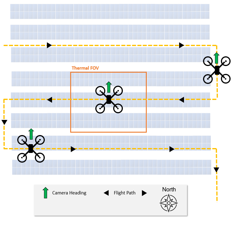
If the module rows are aligned approximately East-West ensure that aircraft faces perpendicular to the course angle (in a general North heading).
If the module rows are aligned approximately North-South ensure that aircraft faces parallel to (i.e. along) the course angle (in a general North heading).
This is set in In "Advanced settings" > "Custom Camera Angle" > "Aircraft Rotate" > Defined
Tip: To set the correct drone heading: During a manual flight, align the solar modules correctly in the frame using the yaw control. Note the heading (in degrees) of the drone/camera on the display. Enter this value as the mission heading
Example North-South course angle, with Aircraft Rotate set parallel to the course angle. Top of captured image will be northerly.
Once the GSD and overlap parameters are set, DJI Pilot 2 will calculate the optimum flight path, but will assume that the target (solar module array) is at the same altitude as the take-off point (ground).
You must specify the "Target Surface to Take Off Point". This does not need to be a precise measurement and can be estimated from the ground. Alternatively use the drone! - fly to the height of the solar array (e.g. roof line) and take note of the reported altitude above take-off. Input this value into the "Target Surface to Take Off Point" .
Flying the mission without specifying a target height will render the data unusable and may result in a collision. Images would have insufficient overlap, inappropriate GSD, and may not cover capture all modules.
Set the "Target Surface to Takeoff Point" altitude after all other parameters are set.
Camera/sensor parameters
Recording Cameras | [Wide] + [IR] |
Course Angle | Parallel to solar rows |
Margin | 0m |
Speed | This is automatically calculated as a function of the mission parameters (Altitude + overlap) Check that the speed does not exceed these maximums, to ensure image quality. M3T Example max speeds -
Speeds for M300/M350 + H20T will be significantly slower due to the increase shutter capture rate (2 seconds vs 0.7 seconds with M3T) |
Image heading | North |
Custom Camera Angle (Gimbal Yaw Direction) | DJI RC Plus with Mavic 3T / M30T/ H20T [Enabled] "Aircraft Rotate" - [Defined] - [0° - magnetic North] If solar module rows do not appear perpendicular in the frame you will need to adjust the camera yaw angle° in the flight planning app (DJI Pilot 2). Pause and restart the mission if necessary. DJI M300 Smart Controller Enterprise + H20T In "Gimbal Settings" select "Free-Mode" This will enable you to set the Yaw of the camera whilst flying a mapping mission. Set the desired camera Yaw (north heading) at first waypoint. The camera should remain fixed in the position whilst the drone rotates around it. You should not have to adjust the heading at the start of each flight row. |
Camera Angle / Gimbal Pitch Rotation | [Defined] - [-90°] (nadir) This is the default setting for mapping missions. |
Thermal file format [I] | R-JPG 640x512 |
RGB file format [W] [Z] | .jpg |
RGB camera exposure | -0.3EV [Wide] |
Capture Mode | Timed Interval Capture |
Emissivity | 0.9 |
Colour Palette | Iron Red |
Gain | -40° to 150° C (High Gain) H20T -20° to 150° C (M3T) |
SBS | "Side-by-side view" <Off> |
Image Super-resolution Mode (IR) *M30T | Disabled |
RTK Maintain positioning accuracy mode | Disabled. |
RTK corrections? | Not essential You may find RTK corrections improve the quality of terrain following modes - reducing the possibility of cropped images. |
Related Articles
Requirements when carrying out a thermographic inspection
For each Inspection zone and Overview zone ✅ Thermal images from radiometric camera [IR] (.JPG) captured during "mapping" mission at the specified GSD ✅ Visual RGB images from wide camera [W] (.JPG) captured simultaneously with "mapping" mission For ...Site Photographs taken during a thermographic inspection
Here are the requirements when it comes to Site photographs taken during a thermographic inspection: Capture at approximately 65m (or lower if flight restrictions dictate) Please capture 2-5 photos. Example site images:Steps to take before a Thermographic Inspection
It is very important to us that we understand your needs and provide you with the most insightful data about your assets. We carry out inspections on thousands of solar plants a year, and our clients have a range of reasons for using our thermography ...What irradiance levels should I have during a thermographic inspection?
The irradiance (nadir - 90° to the module) must exceed 600W/m2 at the time of data capture. Changing weather and cloud cover can mean that irradiance drops below this value. You must be aware of conditions at all times and, if necessary, pause or ...Why has my thermographic inspection data been rejected?
Above provides clear data guidelines to ensure the highest quality of analysis of each solar plant. Please see the issues below to provide context as to why the data could be rejected. Corrupt files When there is a considerable number of frames that ...